AED
AED ALL
ALL ARS
ARS AUD
AUD AWG
AWG AZN
AZN BAM
BAM BDT
BDT BGN
BGN BHD
BHD BRL
BRL BYR
BYR CAD
CAD CHF
CHF CLP
CLP CNY
CNY COP
COP CZK
CZK DKK
DKK DZD
DZD EGP
EGP EUR
EUR FJD
FJD GEL
GEL HKD
HKD HRK
HRK HUF
HUF IDR
IDR ILS
ILS INR
INR ISK
ISK JOD
JOD JPY
JPY KRW
KRW KWD
KWD KZT
KZT LBP
LBP LKR
LKR MAD
MAD MVR
MVR MXN
MXN MYR
MYR NOK
NOK NZD
NZD OMR
OMR PEN
PEN PHP
PHP PKR
PKR PLN
PLN QAR
QAR RON
RON RSD
RSD RUB
RUB SAR
SAR SEK
SEK SGD
SGD THB
THB TND
TND TRY
TRY TTD
TTD TWD
TWD UAH
UAH USD
USD UYU
UYU UZS
UZS VND
VND ZAR
ZAR
Navigation

Those that have followed my modelling activities on the O14 group will know I deliberated for a long time about couplings for my long term O14 project The Pentewan Light Railway (fictitiously rebuilt as a 60cm line in the 1920s). Like many modellers I used USA style knuckle couplers which work very well, however they simply do not look right for the vast majority of British prototypes. I eventually set out to assess a whole range of alternatives and along the way started to make my own. Following several requests I have decided to make them available via this website.
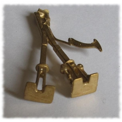
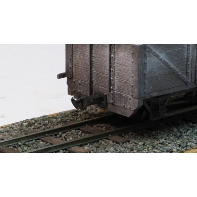
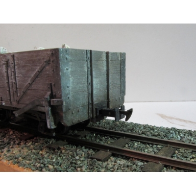
My objective was to make accurate representations of the types of Norwegian chopper couplings used on many UK and Irish mainline narrow gauge railways as illustrated on the following links (which hopefully shows why Knuckle couplers look so wrong on models of such railways): WHR, WLLR, L&BR, IoMR, L&MVLR and T&DR. Chopper couplings were also used extensively in Norway (hence the name), India, Australia, New Zealand and many former British Colonies.
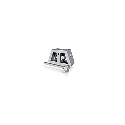
The Jones-Calthrop couplers are almost exactly to scale (1:43.54) and the round and square types are more generic styles. Unlike the prototype all the styles will couple with other. These couplers are supplied with a chopper for one end only, which means all rolling stock needs to face the same way round. This matches common prototype practice. However, if a chopper is raised up out of the way it will couple successfully with another coupler+chopper, i.e. you can have a chopper at both ends, but this will preclude the use of iron tails/ electromagnetic operation on such couplings.
The key operational features of the couplers are as follows:
My objective was to make accurate representations of the types of Norwegian chopper couplings used on many UK and Irish mainline narrow gauge railways as illustrated on the following links (which hopefully shows why Knuckle couplers look so wrong on models of such railways): WHR, WLLR, L&BR, IoMR, L&MVLR and T&DR. Chopper couplings were also used extensively in Norway (hence the name), India, Australia, New Zealand and many former British Colonies.
The Jones-Calthrop couplers are almost exactly to scale (1:43.54) and the round and square types are more generic styles. Unlike the prototype all the styles will couple with other. These couplers are supplied with a chopper for one end only, which means all rolling stock needs to face the same way round. This matches common prototype practice. However, if a chopper is raised up out of the way it will couple successfully with another coupler+chopper, i.e. you can have a chopper at both ends, but this will preclude the use of iron tails/ electromagnetic operation on such couplings.
The key operational features of the couplers are as follows:
- They will autocouple reliably as long as the chopper can successfully find the slot on the face of the mating buffer.
- They will support manual uncoupling via a magnet on a stick acting on an iron wire (supplied) loop in the chopper tip.
- They will support automatic uncoupling via an under track electromagnet acting on an iron wire (supplied) tail.
- They can be made to uncouple via DCC, however currently no components are supplied for this.
- Experiments have shown that delayed uncoupling is also possible using a small latch, however as the optimum shape is yet to determined there are currently no components supplied for this.
- Planning your layout carefully. Coupling may work on gentle curves, but only if the chopper can reliably engage in the slot, whereas uncoupling will only work reliably on straight track.
- Ensuring the chopper, buffer faces and slots are smooth and the chopper can rise and fall freely.
- Accurate fitting both centrally and to a common height – Note that Zamzoodled supply height gauges for this purpose.
- Ensuring the couplings can easily flex sideways and, to a lesser extent, up and down.
I would encourage you to carefully read the instructions which can be downloaded from the Resources page.
If you are interested, my search for suitable couplings, and the initial steps I took towards making my own, were published in Narrow Gauge and Industrial Railway Modelling Review magazine issue no 86. This issue also contains details on prototype chopper couplings. A further article in issue no. 87 covered my attempts at DCC automation.
This is a new venture for me which is carried out in my spare time. I would welcome suggestions for further styles.JC April 2012
Note: Operating mechanisms for DCC are not supplied with the coupling kits.
Note: latches for delayed uncoupling are not supplied with the coupling kits.